When using a 3DeVOK scanner for scanning, how to distinguish between the concepts of accuracy, fineness, and detail?
Accuracy refers to how close a measurement is to the true value, affecting the overall dimensional correctness of the model.
Detail (or fineness/resolution) describes the scanner’s ability to capture and distinguish small features on an object’s surface, reflecting the level of intricacy in the model.
A scan with high detail can clearly show fine surface textures, scratches, and other small features.
- Higher detail/resolution → higher scanning resolution used.
- Higher accuracy → measurements are closer to the true dimensions.
In 3DeVOK Studio scanning software, how to create a background plane for removing desktop data in no marker mode (texture + geometry alignment)?
Before starting the scan, go to “Scan Mode” > “More” > “Common” and enable the “Auto Background Plane” feature.

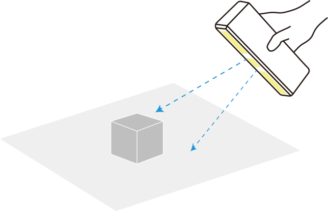
Before starting the scan, position the scanner at a 45-degree angle toward the object, ensuring it simultaneously captures both the object and the desktop surface. This allows the first frame to recognize both the object and the plane, facilitating automatic plane identification by the scanner.
When scanning with marker mode in 3DeVOK Studio scanning software, insufficient markers cause poor alignment, and re-scanning is inconvenient:
①Pause scanning and add markers to sparse areas.
②In the software, enable “Add Mark Points” under “Scan Mode” > “More” > “Common” before resuming.
*Note: New markers aid real-time alignment only and do not affect accuracy calculations. For precision, ensure sufficient markers are attached before scanning.

What should I do if calibration fails or severe data loss occurs with a new device?
New devices are equipped with a transparent protective film on the lens surface. Please remove this film before use.
If issues persist after film removal, please contact technical support for further assistance.![]()
Can damaged or stained scanning markers still be used?
It is not recommended to use damaged or stained markers. Any alteration to their shape or contrast can interfere with software recognition (e.g., in 3DeVOK Studio), potentially causing misalignment, failed marker detection, or errors in the final scan data.
Recommended Actions:
Best Practices:
Replace Promptly: If markers are visibly damaged or dirty, replace them with new, undamaged ones.
Store Carefully: Keep markers clean and properly stored before and after use to avoid contamination.
Apply Properly: Ensure markers lie flat without wrinkles or glare to maximize recognition accuracy
How to choose a turntable for use with a 3D scanner? Are there any specific size recommendations?
Size Selection Criteria:
Core Principle: The diameter of the turntable should be significantly larger than the bottom size of the object being measured.
General Recommendations:
Small objects (e.g., parts, crafts): Recommended turntable diameter of 20-30 cm.
Medium objects (e.g., shoe boxes, helmets): Recommended turntable diameter of 40-60 cm.
For scanning large objects, consider a custom or professional large turntable.
Purchase Suggestions: When selecting a turntable, prioritize the product’s load-bearing capacity and smooth rotation to ensure stability and smooth operation during scanning.
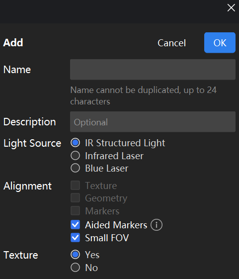
How to Use the Aided Markers Alignment Mode?
– Mode Principle: This mode uses an infrared speckle light source and combines feature points with marker points to achieve stitching, effectively improving scanning stability in environments with insufficient features.
– Stitching Requirements: The scanner must recognize at least 1 marker point in each frame to maintain normal stitching. If stitching is lost, the scanner needs to see at least 2 marker points simultaneously to relocate and restore stitching.
– Marker Placement: Avoid placing two marker points on flat, featureless areas at the same time. It is recommended to place at least one marker point on a feature with distinct curvature or corners.
– Example Application: Infant Head Scanning
This mode is particularly suitable for scanning moving subjects, such as infant heads. Using assisted marker points can effectively counteract stitching loss caused by head movements, making the scanning process smoother. It is also recommended to enable the “Small Scanning Area” mode to limit the scanning range to the head area, avoiding capturing movements below the neck and further ensuring data quality.
How to calibrate the 3DeVOK scanner with a non-matching master plate?
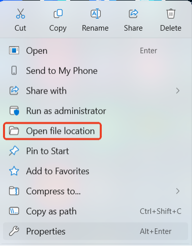
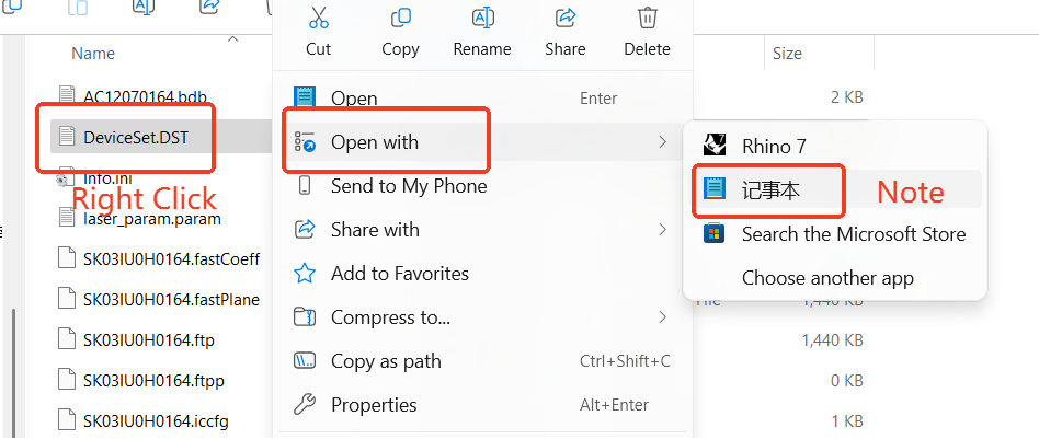
- Right-click the “3DeVOK Studio” icon and select “Open file location”.
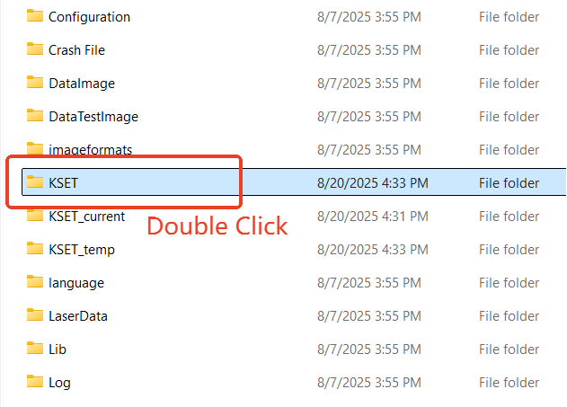
- Find and open the “KSET” folder.
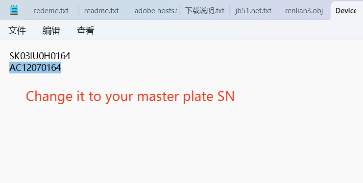
- Inside, find the file “DeviceSet.DST”. Right-click it and open with Notepad.
- You will see two serial numbers:the first line is for the device, the second is for the master plate. Change the second line to the new master plate’s serial number.
- Locate the storage case corresponding to the serial number of the master plateto be used, and retrieve the USB drive inside.
- Open the “KSET” folder on the USB drive.
Copy the “.bdb” file from this folder to the “KSET” folder in the software’s installation directory. (Right-click on the “3DeVOK Studio” desktop shortcut and select “Open file location” to access the installation directory directly)

Why is marker-based alignment in 3D scanners more accurate than texture-based alignment?
Marker-based alignment achieves higher precision than texture-based alignment primarily due to its stable positioning method and stronger resistance to interference.
- Marker-based alignment:
This method involves placing high-contrast fixed markers (such as reflective dots or specially coded points) on the object’s surface, providing the scanner with clear spatial references. These markers have precise and stable positions, ensuring highly accurate alignment of scanned data and minimizing cumulative errors.
- Texture-based alignment:
Texture-based alignment relies on matching visual features such as colors and patterns on the object’s surface. While it can capture rich detail, its performance degrades on smooth surfaces, uniformly colored areas, or repetitive textures. Additionally, environmental factors like lighting and reflections can affect texture stability, further reducing alignment accuracy.
During the scanning process, if the data tracking is lost, how can it be recovered?
For hybrid alignment:
Causes:
- Scanner moved too quickly, resulting in insufficient feature overlap between frames
- Improper scanning distance (too close/far), causing feature recognition failure by the cameras
Solutions:
- Return to a previously scanned area while maintaining the optimal scanning distance
- Pause for 2 seconds to allow the scanner to recognize features and re-establish alignment
Note:
- Begin with feature-rich areas for the first frame to establish a strong reference.
- Pause scanning if alignment fails for >5 seconds, reposition the scanner topreviously captured areas with clear features and resume scanning.
For marker mode:
Causes: Insufficient markers / Marker degradation / Overly regular marker arrangement
Solutions:
- Add several markers in sparse areas and continue scanning, though with reduced positional accuracy. For better results, initiate a new scan with properly distributed markers.
- Remove worn-out markers with alcohol swabs, and replace with new ones.
- Rearrange the existing markers to avoid overly regular placement.
When is it necessary to stick markers when scanning with hybrid alignment?
For objects with limited geometric features and uniform coloration (e.g., car doors), markers must be applied to featureless areas (e.g., flat surfaces) to facilitate scanning and alignment.
Note: To scan objects using markers with hybrid alignment, enable the Laser Fill Light in Scan Mode > Settings > Switch
