What is the purpose of saving project files?
After scanning, you can save scan project files, point cloud project files, and mesh project files for data archiving to prevent data loss and facilitate further processing later.
Saving a scan project file allows you to recalculate starting from the real-time scanning stage; saving a point cloud project file enables you to regenerate the mesh from the point cloud stage; saving a mesh project file lets you reapply texture directly from the mesh stage.


When using a 3DeVOK series scanner with the wireless Airgo for scanning, after powering on by long-pressing the power button, the power indicator light turns on, and the scanner’s touchscreen startup icon lights up. However, the middle indicator light does not illuminate, and the scanner automatically shuts off after a few seconds. Why is that?
It is most likely due to a loose power connection. Please check if the two power interfaces marked in the figure are securely connected. If there is a lanyard, lift the lanyard upward, then firmly insert the cable, tighten the screws, and ensure that both ends of the cable are not loose. Then try powering on again.

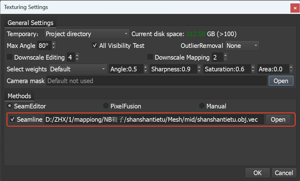
How to retain the previous SeamEditor results when applying textures?
How to retain the previous SeamEditor results when applying textures?
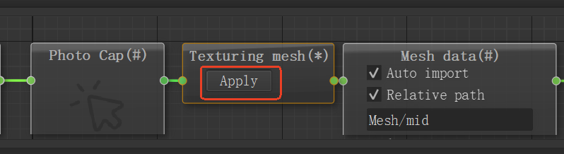
Check the **SeamEditor ** option in the texture settings panel to preserve the previous editing results.
Why the scanner fails to recognize 3mm markers?
If the scanner cannot recognize 3mm markers, it is usually because the option has not been enabled. Please follow these steps:
– Click to enter the “More” settings menu in the software.
– Under “Marker”setting, check whether “3mm Markers” is enabled.
– If it is not enabled: Exit the settings, create a new scanning project, enable “3mm Markers” in the project settings, and then start scanning.
– If it is already enabled but still not recognized: Ensure that the markers are firmly attached, the surface is clean and non-reflective, and retry under good lighting conditions.

By saving the color point cloud as an ASC file, what information can we obtain?
When opening the ASC file with a text editor (e.g., Notepad), you can read three types of core data of the point cloud: three-dimensional spatial coordinates (x, y, z), normal vector parameters (i, j, k), and normalized color information (r, g, b).
In 3DeVOK Studio scanning software, what is the scan preview mode?
The scan preview mode is a real-time calibration step before scanning begins. After clicking “Start Scan” for the first time, the software enters this mode. The interface displays a live view and distance bar, allowing you to adjust to the optimal scanning distance based on the device type (Infrared: 300–400 mm; Blue Light: 210–300 mm). Once the distance is properly adjusted, click “Start Scan” again to exit the preview mode and begin recording 3D data. This feature is enabled by default and effectively improves the success rate of initial scans, which can be disabled in the settings menu.


What are the differences between handheld and desktop 3D scanners? What applications or scenarios is each type best suited for?
Handheld 3D scanners are more flexible and are ideal for scanning complex or large objects, while desktop 3D scanners are more stable and better suited for small objects that require high-precision scanning.
Handheld 3D scanners, such as the 3DeVOK MT and MQ, are operated by the user holding the device during scanning. They offer high flexibility and are especially suitable for complex parts and on-site scanning scenarios where the object cannot be moved. They are widely used in artistic design, reverse engineering, 3D measurement, 3D visualization and display, 3D printing, scientific research, and education, etc.
Desktop 3D scanners use a fixed scanning system combined with an automatic turntable to complete the scanning process. They provide higher stability and are more suitable for high-accuracy scanning of small and precise parts. They are commonly used for quality inspection, product design, and artwork modeling, etc.
What is the resolution of the 3DeVOK MT scanner? Does the resolution affect the level of detail in the final 3D model?
The MT offers three different light source modes: Blue Laser, Infrared Laser, and Infrared Structured Light . Each mode supports different adjustable resolution.
Blue Laser: 0.05–5 mm (adjustable in 0.05 mm increments)
Infrared Laser: 0.1–5 mm (adjustable in 0.1 mm increments)
Infrared Structured Light: 0.1–5 mm (adjustable in 0.1 mm increments)
Different resolution settings will affect the level of detail in the final 3D model.
Generally speaking, a resolution of 0.2–0.3 mm is sufficient to capture enough detail for most applications. The smaller the resolution, the finer the details, but the point cloud processing time will also be longer.
How fast is the scanning speed of the 3DeVOK MT scanner? How long does it take to scan an object?
The MT offers three different light source modes: Blue Laser, Infrared Laser, and Infrared Structured Light.
Each mode has a different point cloud acquisition speed:
- Blue Laser:up to 3,300,000 points/sec
- Infrared Laser:up to 2,450,000 points/sec
- Infrared VCSEL Structured Light:up to 4,500,000 points/sec
The actual scanning time depends on the object size, selected light source mode, point spacing, scanning frame rate, and other settings.
Typical scanning time examples:
Scanning a human torso (spine area): approx. 1 minute
(Light source: Infrared Structured Light; Alignment : Geometry; Resolution: 1.0)
Scanning an artwork (20–30 cm): approx. 2 minutes
(Light source: Blue Laser; Alignment : Texture + Geometry; Resolution: 0.7)
When using the 3DeVOK scanner with the wireless handle for scanning, what is the battery life?
With the standard Nitecore NL2160 6000mAh batteries, two batteries provide approximately 2 hours of continuous operation.
When using a 3DeVOK scanner for scanning, how to distinguish between the concepts of accuracy, fineness, and detail?
Accuracy refers to how close a measurement is to the true value, affecting the overall dimensional correctness of the model.
Detail (or fineness/resolution) describes the scanner’s ability to capture and distinguish small features on an object’s surface, reflecting the level of intricacy in the model.
A scan with high detail can clearly show fine surface textures, scratches, and other small features.
- Higher detail/resolution → higher scanning resolution used.
- Higher accuracy → measurements are closer to the true dimensions.
In 3DeVOK Studio scanning software, how to create a background plane for removing desktop data in no marker mode (texture + geometry alignment)?
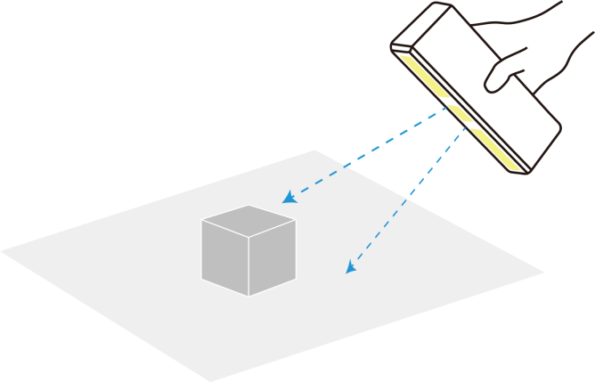
Before starting the scan, go to “Scan Mode” > “More” > “Common” and enable the “Auto Background Plane” feature.

Before starting the scan, position the scanner at a 45-degree angle toward the object, ensuring it simultaneously captures both the object and the desktop surface. This allows the first frame to recognize both the object and the plane, facilitating automatic plane identification by the scanner.