When operating a handheld 3d scanner, it’s common to notice circular black-and-white patches affixed to the objects being scanned. What are these markers, and what purpose do they serve?
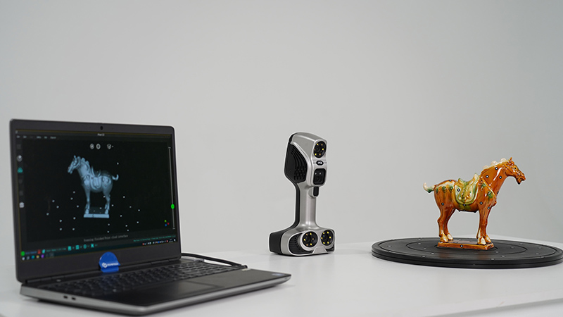
Figure 1: iReal M3 3D Scanning with Markers
The use of a handheld scanner involves dealing with a limited measurement area during each scan. Consequently, aligning data from multiple scans becomes essential.
While several methods exist, including feature-based, texture-based, and hybrid techniques, marker-based alignment is often the preferred choice for small to medium-sized scanners. The circular patches mentioned earlier serve as markers in this context.
So, what are markers?
In the context of 3D scanning, markers are often referred to as ‘reference points’, ‘target points’, or ‘tracking points’. These terms more precisely describe their role in the scanning process. Among these, ‘scanning marker points’ represent a specific category, commonly known as non-coded marker points. Conversely, there are also coded marker points, which contain distinct codes for each marker to enhance precision and tracking efficiency. This discussion will delve into the different types of markers, beginning with an exploration of coded markers.
Coded Markers
Coded markers are widely used in photogrammetric systems, which are based on the principle of capturing images to reconstruct three-dimensional objects in space.
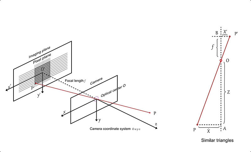
Figure 2 illustrates the basic principles of camera imaging and triangulation, providing a reference for understanding the three-dimensional reconstruction process in photogrammetry.
Figure 2: Camera Imaging Principle and Triangulation Principle
Aerial triangulation, based on photogrammetry, is a common method for three-dimensional reconstruction. Coded markers can serve as a means to calibrate the internal parameters of the camera. During camera calibration for aerial triangulation, multiple photos are taken from various angles, focusing on several coded markers.
Each coded marker point corresponds to a unique code value, providing essential information for image recognition. The internal camera parameters, such as focal length, distortion, and offset, can be determined using triangulation algorithms.
In practical applications, once the camera’s internal parameters are established, the relative positional relationships between scanned objects can be identified.
Figure 3: Common Coding Markers
Figure 3 shows some common coded markers. The central circle or cross provides precise positioning coordinates, while the surrounding circular bands offer coded information that can be decoded according to specific rules.
These marker points function similarly to familiar QR codes, where pre-computed codes for each marker point are captured by the camera and subsequently decoded to determine their unique code values.
Advantages of coded markers include:
Unique Identification: Each coded marker has a unique code, ensuring its uniqueness and avoiding confusion with other markers.
High Precision: Coded information provides more accurate positioning and location information, especially useful for applications requiring high precision, such as industrial measurements and medical imaging.
Automatic Recognition: Scanners or corresponding software can automatically recognize coded markers, eliminating the need for manual intervention and increasing efficiency while reducing the risk of operational errors.
Compared to non-coded markers, photogrammetric techniques using coded markers have a more evident advantage in precision control in large spaces. The above provides some additional knowledge about coded markers.
Non-Coded Markers
Non-coded markers typically refer to the type of markers widely used in the field of 3D scanners, whether it’s a handheld laser scanner from Scantech 3D or a stationary scanner. Marker point alignment is currently considered the most viable solution, and these markers usually adopt a circular design.
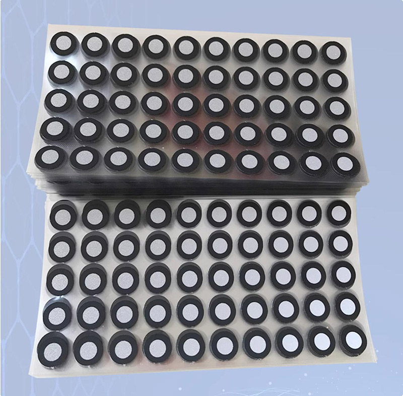
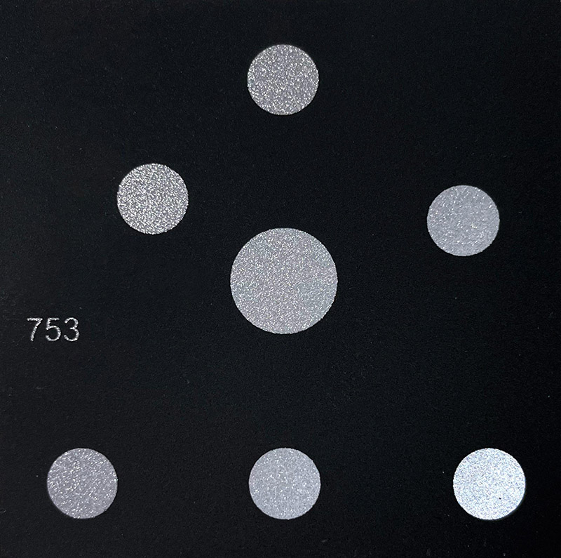
Figure 4: Common Non-coded Reflective Markers
Why choose circular shapes? In machine vision, circular marker stickers appear as ellipses in images, regardless of the shooting angle. More importantly, the center of this ellipse remains constant in space, providing a stable position for determining the center.
In the early days, despite markers having a circular shape, the materials used were relatively simple. In some rudimentary fixed scanners, one could even use a home inkjet printer to print similar circular dots on A4 paper, cut them out, or draw circles with a black pen, and the scanner could recognize them. However, this basic marker point usage in stitching was quite unstable.
At that time, markers were not much different from other materials. The camera, while capturing markers, also easily captured other debris, increasing the risk of misidentification and affecting the quality of the final point cloud reconstruction.
Nowadays, compared to the early days, printing technology has advanced. Markers have clear edges where black and white meet, minimal circularity deviation, and the white inner circle often uses reflective materials, resulting in the current reflective markers.
Although reflective markers may have slightly higher costs, they come with unique advantages. When the camera is underexposed, it can capture the markers and filter the surrounding environment into black, avoiding capturing messy scenes. This reduces the probability of misidentification, saves computational power, and improves scanning speed and accuracy—a win-win situation.
Regarding non-coded markers, there are many variants on the market, such as marker points with different diameters—3mm, 6mm, 12mm. Different diameters are used to address various situations. For instance, too small markers may not be clear in the camera when the scanning distance changes, so different diameters are employed to handle different scenarios.
There are also freely rotatable circular markers that maintain their orientation unchanged, allowing the marker to face any direction at any time. Additionally, there are markers with magnetic properties at the bottom, enabling them to be easily attached to iron surfaces. Further details are not discussed here.
Principles of non-coded marker stitching:
1. Marker Point Groups: Every three markers (1, 2, 3) form a marker group.
2. Alignment Process: When the scanner detects a new marker group (a, b, c), it compares the lengths and angles of the triangle formed by these three points with those of previously known marker groups (1, 2, 3). If their lengths and angles are equal, it can be inferred that the newly discovered three points are actually the previously known (1, 2, 3) points.
3. Establishing Correspondence: Establish a one-to-one correspondence between the newly discovered marker group and the known marker group to ensure they are in the same coordinate system.
4. Data Alignment: Using the established correspondence, stitch the new point cloud data with the previous dataset to form a larger three-dimensional model.
The advantage of this method is that it does not require adding unique coding information to markers. Instead, it relies on geometric shape similarity to determine the correspondence between markers.
In some situations, this approach may be more flexible, especially when markers need to be frequently added or moved.
Insights
Coded markers and non-coded markers are not solely confined to the realms of photogrammetry and structured light 3D scanners.
A notable example of their broader application can be seen in the Scantech KSCAN-Magic series 3D portable scanner, featuring a built-in large-area photogrammetric system.
When it comes to scanning large objects with the KSCAN-Magic scanner, both coded and non-coded markers are utilized to enhance accuracy.
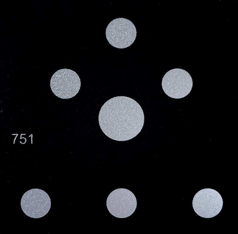
The design of coded markers in the KSCAN-Magic series is particularly unique. Unlike the conventional markers shown in Figure 3, the Magic scanner employs coded markers that are comprised of multiple non-coded markers.
This composition forms a distinct code value for each coded point. These points maintain a central position for precise location determination, as illustrated in Figures 5 and 6.
Additionally, the markers are made with magnetic rubber, facilitating easy attachment to metal surfaces.


