The Full Workflow of Adding Wall Thickness in Geomagic Wrap
04/13/26
Introduction
To solve this problem, it is necessary to repair the scanned model and add wall thickness to make it a closed and manufacturable model.
The scan data used in this article comes from the 3DeVOK MT 3D scanner. The high accuracy and high resolution of the MT scanner can restore the surface details of the object to the greatest extent. High-precision raw data means less manual repair workload in subsequent processing, higher success rate of automatic recognition by Mesh Doctor, and better fitting in offset operations. These advantages will run through the entire wall thickness workflow, significantly improving work efficiency and final model quality.
Next, this article will take a jar-shaped model as an example to introduce in detail the full workflow of adding wall thickness in Geomagic Wrap, including necessary preprocessing and the core operation, aiming to help technical personnel master the complete workflow from open mesh to closed mesh.
1. Preprocessing
Before performing the wall thickness operation, the original scan data must be cleaned and repaired to ensure the stability and accuracy of subsequent operations.
1.1 Model Import and View Operation
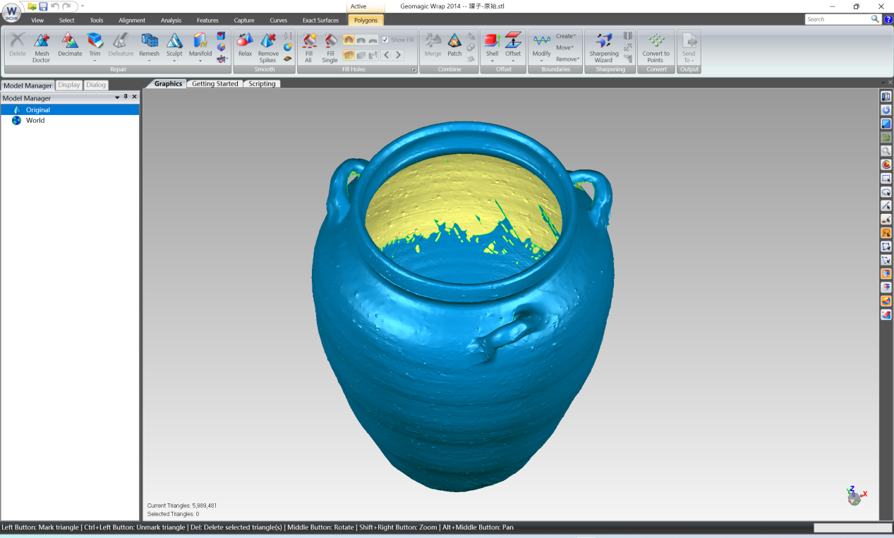
Start Geomagic Wrap, and import the target model through [File] → [Open] (STL format in this example). This 3d data is acquired by the 3DeVOK MT series scanner, with high data completeness and high details, laying a good foundation for subsequent processing.
Basic rules for view operation are as follows:
- Rotate model: Hold the middle mouse button and drag
- Pan view: Hold Alt + middle mouse button and drag
- Zoom view: Scroll the mouse wheel
1.2 Model Decimation
The number of triangles of model can be viewed at the bottom of the software interface. In this example, the original model has about 6 million polygons. For a general computer configuration, direct operation will be very laggy and affect work efficiency. Therefore, the model needs to be decimated:
Click [Polygons] → [Decimate], set the Target Triangle Count to 2 million, and click [Apply] to perform decimation.
Although the number of polygons will be slightly reduced, the smoothness of subsequent operations can be greatly improved. Notably, thanks to the high-precision acquisition of the 3DeVOK MT scanner, even after decimation, the key features of the model are still clearly identifiable and will not affect the alignment accuracy of the wall thickness operation.

1.3 Mesh Doctor Automatic Repair
By observing the model, small spikes, floating triangles, and tiny holes can be found on the surface. At this time, run [Polygons] → [Mesh Doctor]:
After performing the [Mesh Doctor], the software will highlight the detected error areas in red; directly click [Apply] to let the software automatically repair most common errors (such as non-manifold edges, self-intersections, small holes, etc.).
Due to the high quality of the original data, the repair success rate of Mesh Doctor is also improved, and most small defects can be automatically processed at one time. If the running time is too long, check whether the polygon count is too high, or consider repairing in steps.

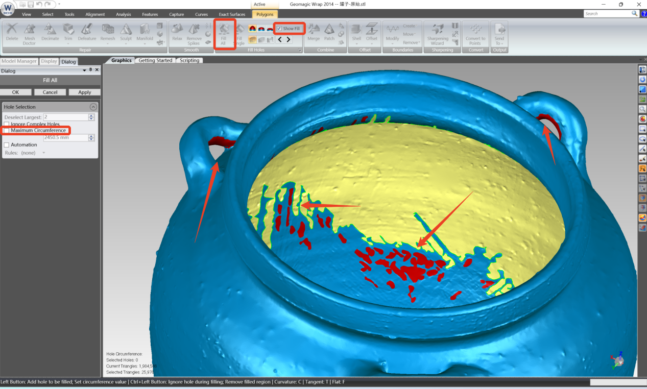
1.4 Hole Filling
Large holes on the model need manual operation:
Click [Polygons] → [Fill Holes]
If [Fill All] is used directly, the software will try to fill all holes, but the effect on very large holes is not good. It is recommended to first check [Maximum Circumference], then click several largest openings on the model in sequence to exclude them from automatic filling;
Click [Apply], at this time all small holes are automatically filled, and only a few large holes are reserved for subsequent processing;
Uncheck [Show Fill] to view the actual state after filling.
2. Core Operation: Adding Wall Thickness
The core idea of adding wall thickness is using the intact inner wall area of the model, through copy, offset, trim, and merge, to ‘cover’ the open gap part and finally form a closed mesh.
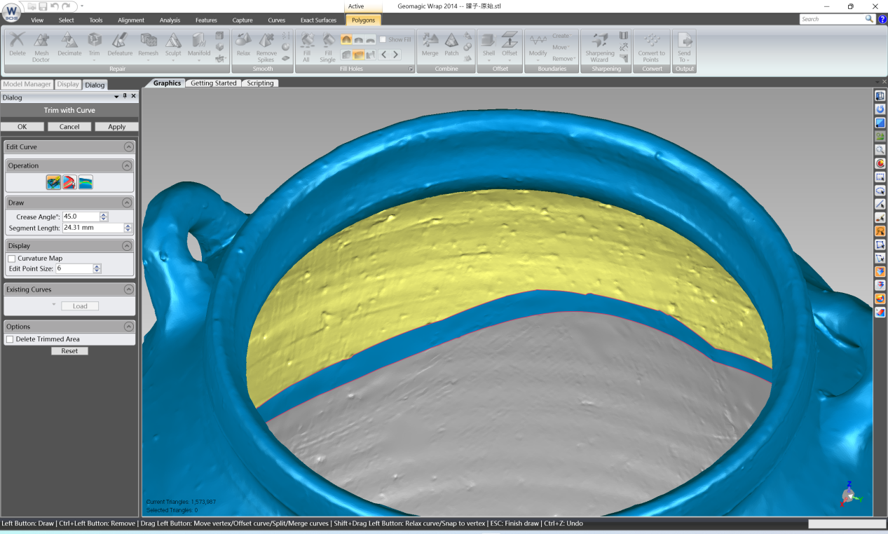
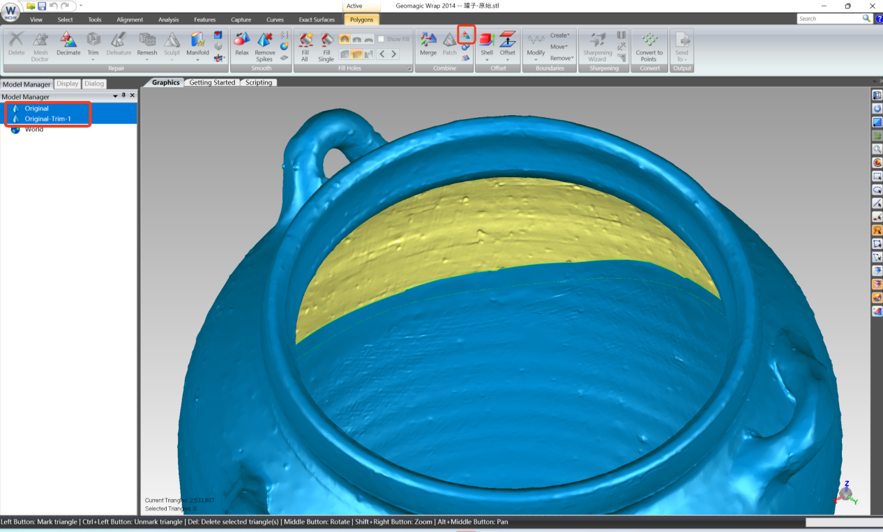
2.1 Flatten the Boundary of the Opening
In order to ensure smooth connection with the main body in subsequent filling, the edge of the large opening needs to be trimmed flat first:
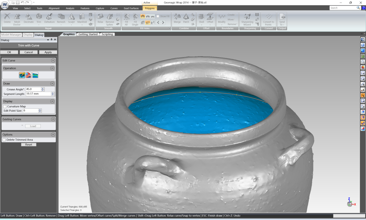
Use [Polygons] → [Trim] → [Trim with Curve]. Near the edge of the opening, click the mouse in sequence to draw a closed curve. The curve needs to be close to the boundary and the start and end must completely coincide. During the drawing process, nodes can be dragged to fine-tune the curve shape;
Click [Apply], the model is divided into two parts;
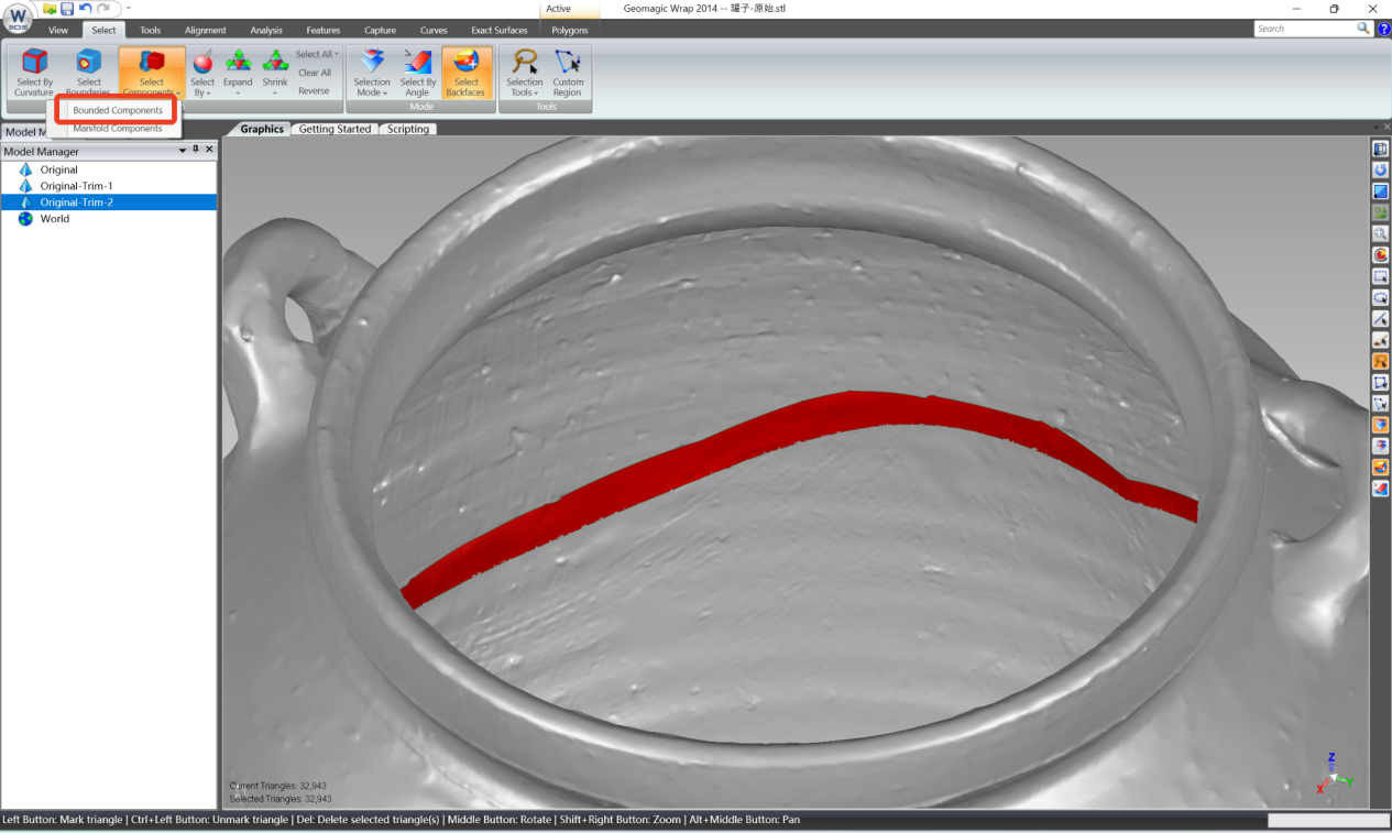
Select the small redundant region at the opening, right-click and choose [Bounded Components], then right-click to delete it, so that the boundary of the opening becomes regular.
2.2 Merge Models
In the Model Manager window, select two models, click [Polygons] → [Combine] to merge them into one.
2.3 Copy and Extract Inner Wall
In the Model Manager window, right-click the current model and select [Duplicate],
Hide the original model and only display the copy;
Use [Trim with Curve] again to trim and delete all parts except the inner wall area corresponding to the opening, and only keep the required inner wall patch.

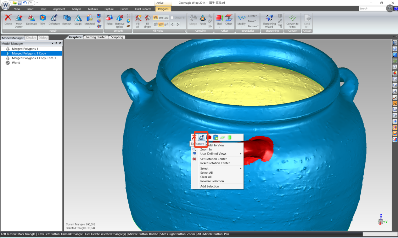
2.4 Remove Internal Interference Structures
In this example, the handle structures of the jar will affect subsequent offset and merge. The processing method is as follows:
In the right-side menu bar, check [Select Through] so that the selection passes through the model;
Use the mouse to box-select part of the handle structure. If other areas are mistakenly selected, hold Ctrl and click to deselect;
Right-click and select [Defeature] to smooth the handles;
Repeat the operation until all handle structures are removed.
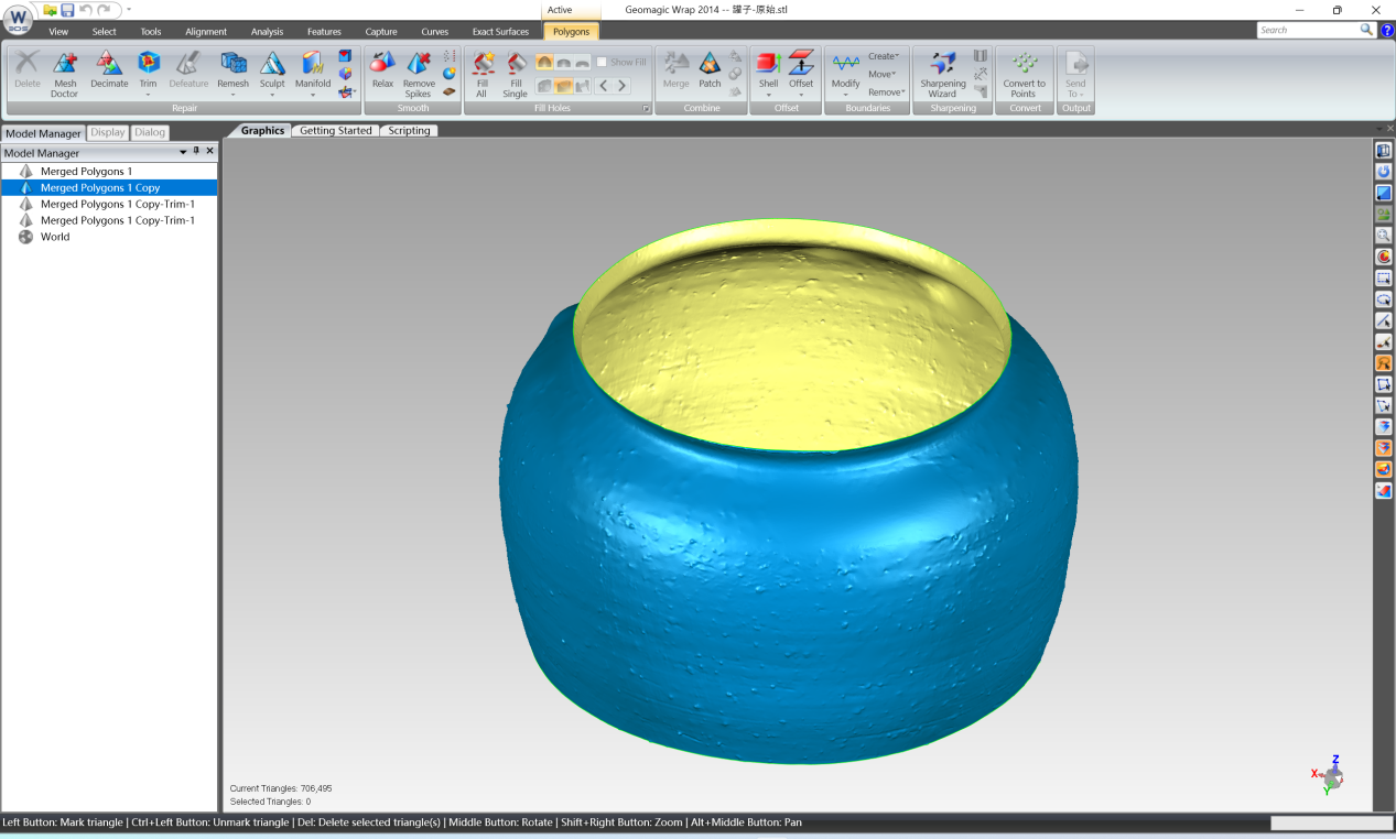
2.5 Offset Inner Wall to the Opening
Re-display the original model and select the trimmed inner wall model;
Click [Polygons] → [Offset] and choose [Smooth] mode. Note that the white arrow on the model indicates the offset direction.

Since the inner wall needs to be offset outward to fit the opening, a negative value (such as -5) should be entered in the value box.
Since the inner wall needs to be offset outward to fit the opening, a negative value (such as -5) should be entered in the value box.
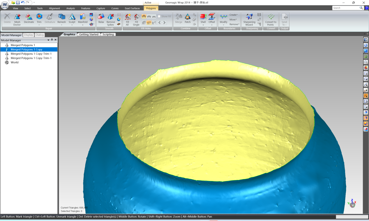
After clicking [Apply], use [View Clipping] under [Display] (enable clipping and drag the slider) to observe from the inside whether the offset is appropriate.
If the offset is too large or too small, undo and adjust the value.
In this example, -4.8 is relatively close, but fine adjustment may still be required. Repeat adjustment until an ideal offset effect is obtained.
Thanks to the high-precision acquisition of the 3DeVOK MT scanner, the geometric features of the original model are clear and deformation is minimal. Therefore, during the offset fitting process, even after multiple adjustments, the model can still maintain good shape consistency without distortion caused by poor data quality.
 2.6 Flip Normals and Secondary Trimming
 2.6 Flip Normals and Secondary Trimming
If the offset inner wall appears orange, it indicates that the normal direction is incorrect. Use [Polygons] → [Repair Tools] → [Flip Normals] to correct it.
 Use [Trim with Curve] again, along the boundary of the original opening, to trim off the redundant parts of the offset model, and only keep the area that can exactly fill the opening.
At corners, some buffer area can be appropriately reserved to facilitate subsequent blending.
2.7 Merge Models and Final Repair
In the Model Manager window, hold Ctrl to select the original model and the trimmed patch, right-click and select [Merge] to combine them into one.
After merging, small gaps may remain. Use [Polygons] → [Fill Holes] → [Fill Single Hole], first perform [Bridge] at the gap, then guide the software to automatically fill the hole. Bridging is an effective method for filling internal holes.
After all holes are repaired, run [Mesh Doctor] again to perform a full inspection and repair of the model to ensure mesh quality.

2.8 Save Model
After confirming the model is correct, use [File] → [Save] to export the data in the required format (such as STL, 3DP).
3. Summary
This article describes in detail the technical workflow of converting an open scan model into a closed mesh by adding wall thickness in Geomagic Wrap.
Key points include:
- Preprocessing is essential, laying the foundation through decimation, Mesh Doctor, and hole filling
- The key to adding wall thickness is to use intact inner wall areas, and achieve precise filling through copy, offset, trim, and merge
- The offset value needs to be repeatedly verified with View Clipping to ensure fitting accuracy
- Final inspection is completed by running Mesh Doctor again to ensure model quality
It should be emphasized that the efficiency and final result of the entire wall thickness workflow are closely related to the quality of the original scan data. The 3DeVOK MT 3D scanner used in this example provides a high-quality data foundation with its high-precision acquisition capability, significantly reducing manual repair workload and improving offset fitting accuracy.
By mastering the method described in this article and combining it with high-quality scan data, most open model problems caused by incomplete scanning can be effectively handled, providing high-quality solid data for applications such as 3d printing and reverse engineering.
Related Articles


View Our Product
